HLS Lab 2: An audio filter on the DE1-SoC board
Based on the original lab by Yves Mathieu (Télécom Paris).
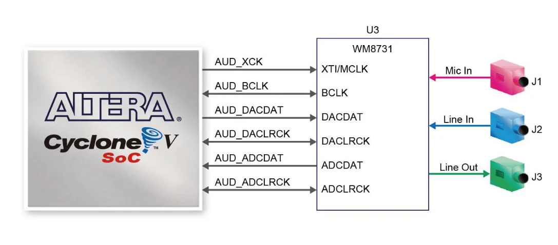
The DE1-SoC board has a Wolfson WM8731 audio codec connected to its Cyclone V FPGA. You will turn a FIR low-pass filter, generated as plain C by a web tool, into a hardware block that removes an 8 kHz tone from a piano recording in real time, then control it from the Nios II processor and investigate how loop unrolling changes throughput and area.
1. What you will learn, and why HLS here
- Write a component with Avalon Streaming (Avalon-ST) interfaces and check it against a software reference.
- Turn a real-time requirement into a cycle budget, and check the hardware against it with the initiation interval (II).
- Read the reports to find what limits the II, and fix it.
- Integrate an HLS component into a Nios II system, and control it through an Avalon Memory-Mapped (Avalon-MM) register.
- Investigate the throughput–area tradeoff by comparing the 50 MHz baseline with a guided unroll-2 variant.
Why HLS for this filter? The algorithm already exists as C. The interfaces are standard (Avalon-ST to the audio core, Avalon-MM to the CPU). And the right architecture is not obvious: one multiplier or many, shared memories or not, which widths. In RTL each of those choices is a rewrite; here most are a few lines of C++. That is the situation HLS was made for.
The number to keep in mind
The board clock is 50 MHz and the codec delivers one stereo frame at 48 kHz. That is 20.8333 μs per frame, or 1041.667 clock cycles. The component must accept a new frame at least this often. Once it meets that budget, a lower II is extra speed, not a real-time requirement.
| Step | What you do | What it teaches |
|---|---|---|
| STEP0 | Get the files | |
| STEP1 | Design and test the filter in plain C++ | The golden reference |
| STEP2 | Build a passthrough system on the board | Platform Designer, the audio IPs, timing |
| STEP3 | Turn the filter into an HLS component; measure it | Streams, reports, II, the effect of the clock target |
| STEP4 | Put the filter on the board | Integrating an HLS IP |
| STEP5 | Add a bypass register driven by the Nios II | Avalon-MM agent registers |
| STEP6 | Explore architectures; report | Design space exploration |
Boxes marked Predict ask you to write down an expectation before running something. Keep a lab notebook: STEP6 builds on the numbers you record in STEP3.
2. STEP0: The initial archive
Download the tar archive and extract it in a work directory.
| Directory | Used in | Content |
|---|---|---|
software_demo/ |
STEP1 | Pure C++ version of the filter: the golden reference. Don't modify it after STEP1. |
DE1_SoC_filter/ |
STEP2, 4, 5 | Quartus project with a Nios II system; control-soft/ holds the Nios program |
HLS/ |
STEP3–6 | Where you write the HLS component. Contains only a Makefile at first |
waves/ |
all | Audio files: the original, the noisy version, and a 10 ms extract |
wavelib/ |
all | A small library to read and write .wav files |
tools/ |
STEP3, 6 | wavecmp.cpp, compares two .wav files sample by sample |
3. STEP1: A pure software filter
Open a terminal in software_demo/. Running make lists the targets. Don't compile anything yet. Plug your headphones into the workstation.
3.1 Listen to the sequences
make play_original_wave
make play_noisy_wave
The first is a short piano sequence. The second is the same with a continuous 8 kHz tone added. If you hear nothing, ask for help configuring your session.
Note it down
What is the sampling frequency of the files? (mpv prints it when it starts playing.) You need it in 3.2 and in STEP2.
3.2 Design a FIR low-pass filter
Open the online FIR filter generator TFilter. In the lower-left panel:
- Set sampling freq. to the sampling frequency of the files.
- Set desired #taps to 256.
- First band (pass band): from 0 Hz to 7000 Hz, gain 1. Keep the default ripple.
- Second band (stop band): from 7750 Hz to half the sampling frequency, gain 0. Keep the default attenuation.
- Click DESIGN FILTER.
The page plots the frequency response; the Impulse Response tab shows the 256 taps.
Checkpoint
Read the attenuation at 8 kHz on the frequency response. The tone may be difficult to hear even when the stop-band attenuation is visible. For ideal symmetric taps a FIR has linear phase, but check how this implementation aligns its circular history before predicting the observed delay; do not change the historical indexing.
Now get the source code:
- Open the skeleton files
SampleFilter.cppandSampleFilter.hin your editor. - Open the Source code tab of TFilter.
- Set Number format to integer and Fixed point precision of taps to 32 bits. With these settings, TFilter scales the coefficients by 2^31 while the generated filter shifts the accumulator by 32 bits. The resulting passband gain is approximately 0.5 (−6 dB). This setting does not change the number of taps or the C storage width.
- Copy the generated code into
software_demo/SampleFilter.cppand.h, then save. The student archive contains skeleton files. Keep the generated filter insoftware_demo/as the software reference; copy it intoHLS/only when asked.
Keep the page open, in case you need to regenerate the code.
Check the generated code
Confirm that the generated C code uses integer taps, integer history, a 64-bit accumulator and acc >> 32. If any of these differ, recheck the TFilter selections before proceeding. Keep the same generated filter as the software reference throughout the lab.
3.3 Read the reference program
Open main.cpp. This is a regular C++ program, not HLS yet. You will adapt it in STEP3.
Identify the main parts:
main()reads the stereo WAV file usingwavelib, converts the audio samples to 24-bit signed integers, calls the filter, and writes the resulting WAV file. The conversion details are handled by the supplied code.audio_filter()processes one stereo frame (one left and one right sample). It uses two separateSampleFilterobjects, one for each channel. They are declaredstaticso they retain their history between calls.SampleFilter_put()andSampleFilter_get()store the new sample and compute the filtered output using the 256 coefficients and previous samples.
The important point is that each new audio sample requires 256 multiply-accumulate operations. This repeated computation is what we will accelerate using HLS.
Do not modify the reference program. We will use it later to verify the hardware implementation.
3.4 Build and listen
make test-sample-conversion
make test
make gen_filtered_wave
make gen_short_filtered_wave
make play_filtered_wave
The first recording is a piano sequence; the second includes an additional 8 kHz tone. Depending on your headphones and hearing, the difference may be difficult to notice.
If you cannot hear it clearly, you can compare the recordings using an online audio comparison tool. The goal is simply to identify the unwanted tone that our FIR filter will remove.
The sample-conversion test should print PASSED. It checks that 16-bit WAV samples are correctly converted to the 24-bit signed format used by the audio codec, including extreme values.
The other commands compile the software filter and generate both the full filtered recording and a short 10 ms version. The short version will be used later for HLS simulation.
Listen to the filtered recording. The 8 kHz tone should be attenuated, although the difference may be difficult to hear.
Keep these generated WAV files: they serve as the reference for checking the HLS implementation in STEP3. If you change the filter coefficients, regenerate the reference files before comparing.
4. STEP2: A passthrough on the board
Before adding the filter, build a system in which the board copies its line input to its line output.
- In
DE1_SoC_filter/, launch quartus and openDE1_SoC.qpf(File → Open Project). - In the Project Navigator, switch from Hierarchy to Files.
- Double-click
cpu_system.qsysto open Platform Designer.
cpu_system already contains a Nios II processor, on-chip RAM, a JTAG UART and two PIOs (LEDs and switches). You will add three University Program IPs to reach the codec.
4.1 The audio core
In the IP catalog, find Audio under University Program → Audio & Video.
- Add it. In its configuration, set Interface Settings to Streaming and Data Format to 24 bits.
- The block diagram shows an external interface (to the codec), two Avalon-ST sinks (left and right, towards the DAC) and two Avalon-ST sources (left and right, from the ADC).
- In System Contents:
- connect its
clktoclk_0.clkand itsresettoclk_0.clk_reset; - connect
avalon_left_channel_sourcetoavalon_left_channel_sink, and the same for right: this is the passthrough; - export
external_interfaceand name it audio.
- connect its
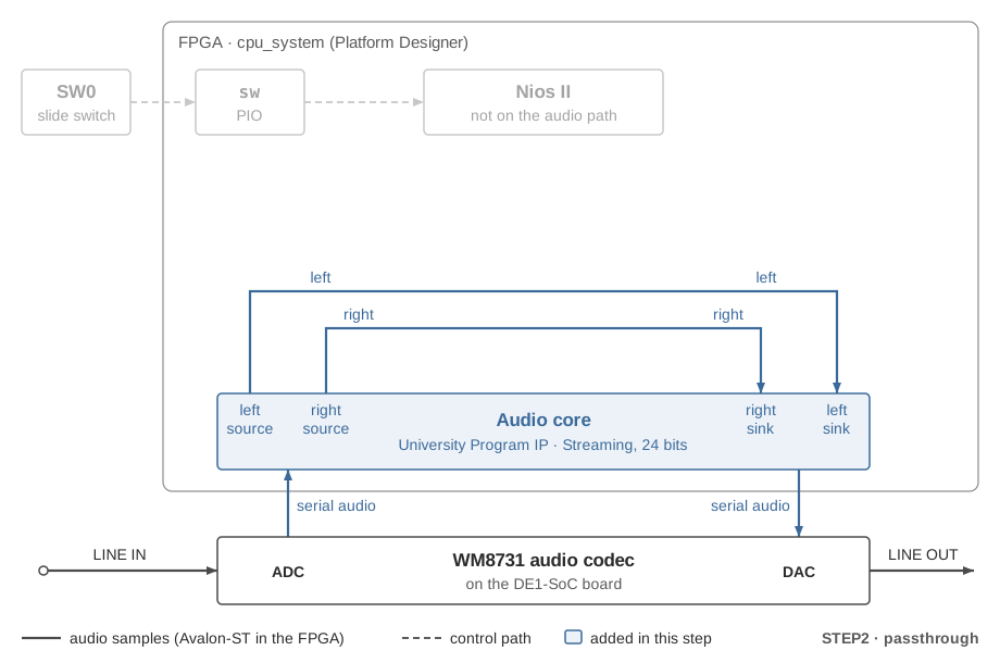
An Avalon-ST link has no addresses: the source drives data and valid, the sink drives ready, and one sample moves on each clock edge where valid and ready are both high. HLS generates this protocol for you. For the details, see the streaming chapter of the Avalon Interface Specifications.
4.2 The audio clock
The codec needs its own master clock. In University Program → Clock, find Audio Clock for DE-series Boards.
- Add it and keep the default parameters (12.288 MHz for 48 kHz audio).
-
In System Contents, make the following connections:
Source Destination clk_0.clkAudio Clock ref_clkclk_0.clk_resetAudio Clock ref_resetAudio Clock reset_sourceAudio core reset -
Export the Audio Clock
audio_clkinterface and name it audio_clk.
The ref_reset input resets the clock generator, while reset_source is an output used to reset the audio components. Use the instance names displayed in your system.
4.3 The codec configuration
The FPGA configures the codec over I2C at start-up. In University Program → Audio & Video, find Audio and Video Config.
- Set DE Board to DE1-SoC and tick Auto Initialize Devices (static configuration at reset).
- Set Audio In Path to Line In to ADC. Check that Bit Length is 24 bits, Sampling Rate matches the files, and audio output to the DAC is enabled (the tested system has
audio_out=trueanddac_enable=true). - Click Finish. Connect its
clkto the system clock, and itsresetto bothclk_0.clk_resetand the audio clock'sreset_source. - Export
external_interfaceand name it audio_cfg. - Leave
avalon_av_config_slaveunconnected. Platform Designer warns about it; that is expected.
4.4 Update the Quartus project
- In Platform Designer: File → Save, then Generate → Generate HDL.
- Open
cpu_system/cpu_system_inst.vand use it to identify the generatedcpu_systemport names. It is a template; do not edit it. -
In
DE1_SoC.sv, add the required ports to the actualcpu_system u0 (...)instance at the end of the file. The board's pin names are declared at the top of the module:cpu_systemportTop-level signal ( DE1_SoC.sv)audio_ADCDAT,audio_ADCLRCK,audio_BCLK,audio_DACDAT,audio_DACLRCKaud_adcdat,aud_adclrck,aud_bclk,aud_dacdat,aud_daclrck(under/// AUD ///)audio_clk_clkaud_xckaudio_cfg_SDAT,audio_cfg_SCLKfpga_i2c_sdat,fpga_i2c_sclk(under/// FPGA ///)Then delete the line
assign fpga_i2c_sdat = 'z;above the instance: it kept the unused I2C pin in high impedance, and the codec configuration IP now drives that pin. -
Compile the project (Processing → Start Compilation). A successful compile alone does not prove the external audio pins are connected: inspect warnings for undriven codec data/clock, audio master clock and I²C ports, then verify the
DE1_SoC.svinstance mapping above. In a correctly connected system, the only such warnings say that the bidirectional clock pinsaud_adclrck,aud_bclkandaud_daclrckhave no driver; the codec drives those clocks. Treat any warning aboutaud_adcdat,aud_dacdat,aud_xck,fpga_i2c_sclkorfpga_i2c_sdatas a missing connection. - Open the Timing Analyzer summary in the compilation report.
clock_50must appear as a 20 ns clock with positive setup and hold slack. A design that fails timing can work on one board and not on another.
4.5 Test on the board
- In
control-soft/, program the FPGA:make fpga-conf - Connect the workstation's headphone output to the board's LINE IN (blue) with a cable, and your headphones to the board's LINE OUT (green).
- Play one of the STEP1 sequences from the workstation. You should hear it through the board, unchanged.
Close Quartus.
5. STEP3: The filter as an HLS component
From DE1_SoC_filter/, start bash, initialize Intel HLS, and copy the reference program and filter into HLS/:
bash
source /comelec/softs/opt/altera/current/hls/init_hls.sh
cd ../HLS
cp ../software_demo/main.cpp ../software_demo/SampleFilter.h ../software_demo/SampleFilter.cpp ../software_demo/audio_sample.h .
From now on, modify only the copies in HLS/. software_demo/ stays the reference. For host emulation, use make CXX=/usr/bin/g++ test-gpp if the selected g++ fails to link. The HLS Makefile defaults GCC_TOOLCHAIN to /usr; if i++ cannot link with that toolchain, use the installed alternative documented in the Makefile: make GCC_TOOLCHAIN=/comelec/softs/opt/altera/altera24.1/gcc test-fpga.
5.1 The audio_filter component
Samples are 24-bit signed integers, and the Algorithmic C datatypes give you that type exactly. Add at the top of HLS/main.cpp:
#include "HLS/hls.h"
#include "audio_sample.h"
#ifdef __INTELFPGA_COMPILER__
#include "HLS/ac_int.h"
#else
#include "ref/ac_int.h"
#endif

typedef ac_int<24, true> audio_sample;
Intel HLS provides two templated stream types: ihc::stream_in for an Avalon-ST sink, ihc::stream_out for a source. Define:
typedef ihc::stream_in <audio_sample, ihc::bitsPerSymbol<8>> audio_stream_in;
typedef ihc::stream_out<audio_sample, ihc::bitsPerSymbol<8>> audio_stream_out;
bitsPerSymbol<8> says the 24-bit sample travels as three 8-bit symbols, which is how the audio core sees it.
Replace the audio_filter function by a component with four streams:
component void audio_filter(audio_stream_in  &audio_left_in,
                            audio_stream_in  &audio_right_in,
                            audio_stream_out &audio_left_out,
                            audio_stream_out &audio_right_out) {
  static SampleFilter left_filter, right_filter;

  audio_sample left_sample = audio_left_in.read();   // waits for a valid sample
  SampleFilter_put(&left_filter, left_sample);
  left_sample = SampleFilter_get(&left_filter);
  audio_left_out.write(left_sample);                  // waits until the sink is ready

  audio_sample right_sample = audio_right_in.read();
  SampleFilter_put(&right_filter, right_sample);
  right_sample = SampleFilter_get(&right_filter);
  audio_right_out.write(right_sample);
}
read() and write() are blocking: in hardware they wait on valid and on ready. One call filters one stereo frame. The filter code stays exactly as TFilter generated it, for now.
5.2 Adapt the testbench
The component takes streams, so the testbench works in three phases:
- write all the input samples into the input streams;
- queue one call of the component per stereo frame, then run them all;
- read all the results from the output streams.
At the start of main, declare the four streams and keep them local to main (do not declare them globally):
audio_stream_in  to_audio_left_in;
audio_stream_in  to_audio_right_in;
audio_stream_out from_audio_left_out;
audio_stream_out from_audio_right_out;
Replace the split loop (remove left_content and right_content):
const float FULL_SCALE = 8388608.0f; // 2^23
for (std::size_t i = 0; i + 1 < content.size(); i += 2) {
  to_audio_left_in.write (normalized_float_to_signed24(content[i]));
  to_audio_right_in.write(normalized_float_to_signed24(content[i + 1]));
}
Copy the normalized_float_to_signed24 helper from audio_sample.h into the testbench, or include that header. It multiplies the decoded float by 2^23, truncates toward zero, and saturates at the signed 24-bit endpoints. Use the same helper for software and HLS testbench inputs.
Why clamp before converting?
The policy is explicit because the WAV library's normalization places PCM16 endpoint values outside the signed 24-bit range after scaling. Conversion through int truncates toward zero, but only after clamping; without the clamp, +32767 and −32768 can overflow or wrap.
Replace the filtering loop by one queued call per frame, then run them all:
for (std::size_t i = 0; i < content.size() / 2; ++i) {
  ihc_hls_enqueue_noret(&audio_filter,
                        to_audio_left_in, to_audio_right_in,
                        from_audio_left_out, from_audio_right_out);
}
ihc_hls_component_run_all(&audio_filter);
ihc_hls_enqueue_noret is the version of ihc_hls_enqueue for components that return nothing. Queuing the calls lets the co-simulation issue them back to back, so it shows the component's real throughput.
Finally, build the output from the output streams:
std::vector<float> content_out;
for (std::size_t i = 0; i < content.size() / 2; ++i) {
  audio_sample left_sample  = from_audio_left_out.read();
  audio_sample right_sample = from_audio_right_out.read();
  content_out.push_back(left_sample.to_int()  / FULL_SCALE);
  content_out.push_back(right_sample.to_int() / FULL_SCALE);
}
From C++ to HLS: what changed?
The FIR algorithm is unchanged, but its interface and execution model are different.
| Original C++ | HLS version | Why? |
|---|---|---|
void audio_filter(...) |
component void audio_filter(...) |
Defines a function to synthesize into hardware |
int |
ac_int<24, true> |
Uses exactly 24 bits for each audio sample |
Pointer arguments (int*) |
ihc::stream_in / ihc::stream_out |
Creates hardware streaming interfaces |
| Read/write through pointers | .read() / .write() |
Receives and sends samples using the Avalon-ST protocol |
| Direct function call | ihc_hls_enqueue_noret() and ihc_hls_component_run_all() |
Tests repeated hardware component invocations in simulation |
Remember: Only the HLS component is synthesized into hardware. The main() function, WAV file handling, and ihc_hls_* calls belong to the software testbench.
5.3 Functional test
make test-gpp
make gpp_gen_filtered_wave
make compare
make compare builds tools/wavecmp and compares your output with the STEP1 reference. It must print PASSED: same samples, same channels. If it says the files would match with left and right exchanged, check your split loop. You can also listen: make play_gpp_filtered_wave.
5.4 Synthesis and co-simulation
make test-fpga
make fpga_gen_short_filtered_wave
make compare-short
make test-fpga runs i++. It also fixes one property of the generated streams with sed (firstSymbolInHighOrderBits): the byte order of the three 8-bit symbols must match the audio core's. If you ever run i++ by hand, apply the same fix.
Co-simulating the whole sequence would take very long, so fpga_gen_short_filtered_wave runs only the 10 ms extract (480 frames). make compare-short checks it against the software reference generated from the same filter. If that short reference is stale after changing the software filter, regenerate just that file from HLS/ with make -C ../software_demo -B ../waves/piano2_short_filtered.wav, then rerun make compare-short. This target rebuilds the software test and the 10 ms reference without cleaning other generated files.
5.5 Read the reports, then predict
make show-syn-results
Open Throughput Analysis → Loop Analysis. It lists the component and its loops: one loop for each call of SampleFilter_get, so one per channel. Loop II is the tap-loop interval; component II is the interval between accepted stereo-frame calls and includes both channels and surrounding work.
Predict
Note each loop's II and, when it is above 1, the reason given in the details pane. Then, with cycles ≈ (N − 1) × II + L for a loop of N iterations, estimate the loop cycles. Use the component report to determine the full stereo-frame II; the loop estimate is not the component II. Is it under the 1041-cycle budget?
First write a prediction. The default scheduler target is approximately 240 MHz. Inspect the recurrence and memory-port diagnostics in your report to explain the measured loop II and component II. Do not infer component II from loop II alone. HLS scheduler estimates and target fMAX are not Quartus post-fit timing.
5.6 Measure
On the waves. Run make show-waves.
- Add all the signals of the
audio_filterinstance to the Wave window and zoom to fit (key F). - Set
audio_left_in_dataandaudio_left_out_datato radix decimal and format Analog. Compare the input and output, but interpret data only on valid transfers. The HLS pipeline latency is not the audio filter group delay; the history indexing also affects the observed sample alignment. - Zoom in on two consecutive samples. Find the clock edges where
audio_left_in_validandaudio_left_in_readyare both high: each one is a sample entering.
Measure
- II: the number of cycles between two consecutive samples entering on
audio_left_in. - Latency: the number of cycles from a sample entering on
audio_left_into its result leaving onaudio_left_out(validandreadyboth high).
Count a sample transfer only on a clock edge where valid and ready are both high. If valid is high while ready is low, the sample is pending: the source must keep valid and data stable until the sink accepts it. Ignore data when valid is low; a stalled sample has not yet transferred.
In the reports. Reload them and open Throughput Analysis → Verification Statistics, filled in by the co-simulation: the measured latency and II of the component.
Start your results table. You will add rows to it in 5.7 and in STEP6.
| Variant | Loop II | Component II (measured) | Latency | Within 1041? | compare |
|---|---|---|---|---|---|
| V0: as generated |
Checkpoint
Do your prediction, your waveform measurement and the Verification Statistics agree? If not, explain the difference.
5.7 Give the tool the real clock
The board runs at 50 MHz, not at the frequency i++ assumes. Tell the scheduler: in HLS/main.cpp, put this attribute on the line just before component void audio_filter(...):
hls_scheduler_target_fmax_mhz(50)
Predict
Predict the MAC loop II and full component II at 50 MHz. Explain how allowing a longer clock period can let the recurrence complete in one cycle and reduce II, even though the requested clock is slower.
Rebuild and re-run: make test-fpga, make fpga_gen_short_filtered_wave, make compare-short, then reload the reports. Add the row V1: target 50 MHz to your table.
Checkpoint
Was your prediction right? Explain from the report how the longer target period affects the recurrence-limited loop II and whether the measured component II fits the 1041.667-cycle budget. A lower scheduling target may allow the accumulator recurrence to complete in one scheduled cycle, improving throughput in cycles.
Record the scheduler target, loop II and latency, component II and latency, scheduler-estimated fMAX, dependency diagnostic, HLS resource estimates and correctness. Keep these separate from Quartus fitted resources, post-fit timing and audio sample/group delay.
6. STEP4: The filter on the board
- In
DE1_SoC_filter/, make your component visible to Platform Designer:make add_filter_component - Open the project in Quartus and
cpu_system.qsysin Platform Designer. The IP catalog now has an HLS folder containing audio_filter. - Add
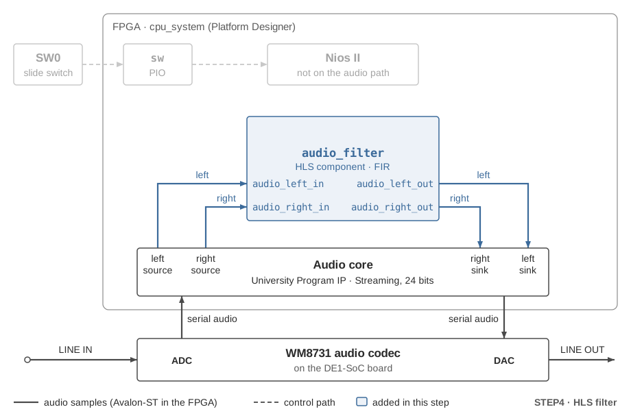
audio_filter. Connect itsclockandresetto the system clock and reset. - Remove the passthrough connections and insert the filter:
audio_1.avalon_left_channel_source→filter_0.audio_left_in;audio_1.avalon_right_channel_source→filter_0.audio_right_in;filter_0.audio_left_out→audio_1.avalon_left_channel_sink; andfilter_0.audio_right_out→audio_1.avalon_right_channel_sink. - Export the filter's call conduit and name it call. Leave the return conduit unconnected; Platform Designer then warns that
filter_0.returnmust be exported, which is expected. - Save and generate the HDL.
- In
DE1_SoC.sv, add the two newcallports fromcpu_system_inst.v:.call_valid (1'b1): the filter is always called. It starts a new call as soon as it can, forever..call_stall (): left unconnected.
- Compile, check the Timing Analyzer summary as in 4.4, program the board (
make fpga-confincontrol-soft/) and play the noisy sequence.
You should hear the piano without the tone.
Optional: hear the budget
Program the board with the V0 version (without the attribute of 5.7). If its II was above 1041, what do you hear, and why? After this experiment, restore hls_scheduler_target_fmax_mhz(50) in HLS/main.cpp before starting STEP5.
After any change to the C++, the board sees it only if you redo the whole chain: make test-fpga, make add_filter_component, regenerate HDL in Platform Designer, recompile, reprogram.
7. STEP5: Driving the filter from the Nios II
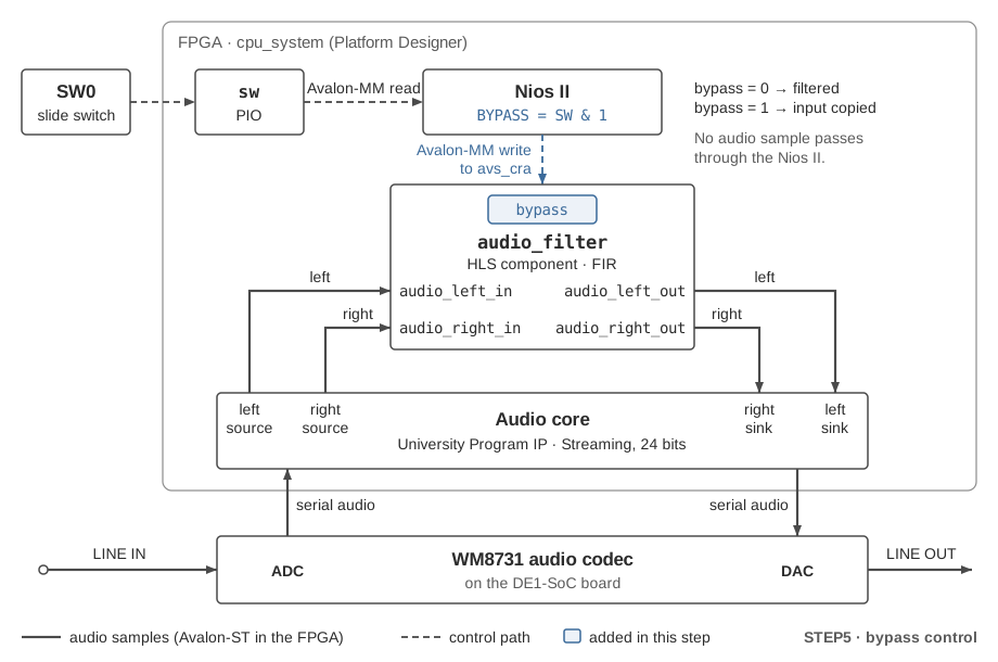
The Nios II will control the filter through one register, bypass:
- bypass = true: the component copies its input samples to its outputs;
- bypass = false: it filters them.
Before changing the HLS sources, save the STEP3 version for the STEP6 comparison. The student archive does not include an instructor .baseline file. From HLS/, run:
mkdir -p pre_bypass
cp main.cpp SampleFilter.cpp SampleFilter.h pre_bypass/
7.1 Modify the component
Add a first argument to the component:
component void audio_filter(hls_avalon_agent_register_argument bool bypass,
                            audio_stream_in  &audio_left_in,
                            ...
hls_avalon_agent_register_argument puts bypass in a persistent register written over Avalon-MM. HLS captures its value when a call is accepted (start while not busy); a write does not change a call already accepted. The first audio frame affected depends on write timing and calls in flight, so do not assume an immediate switch. (Older code spells it hls_avalon_slave_register_argument; that name still works in 21.4 but is deprecated.) Change the body so the output depends on bypass.
Design choice
The reference policy is to keep updating both filter histories in bypass mode, then select the unfiltered sample for output. If the histories are frozen, switching back to filtering uses stale samples and creates a transient. Implement the reference policy and explain why.
In the testbench, pass the new argument in the queued calls:
ihc_hls_enqueue_noret(&audio_filter, true,
                      to_audio_left_in, to_audio_right_in,
                      from_audio_left_out, from_audio_right_out);
Test both values of bypass in software (headphones back on the workstation):
make test-gpp
make gpp_gen_filtered_wave
make play_gpp_filtered_wave
With false, make compare must still print PASSED. With true, the output is the noisy input within one PCM16 LSB: ../tools/wavecmp ../waves/piano2_noisy.wav ../waves/gpp_piano2_filtered.wav 1 passes. The supplied reader normalizes PCM16 by 32767; the comparator quantizes decoded values back to PCM16 integer codes before measuring error.
Then synthesise and co-simulate:
make test-fpga
make fpga_gen_short_filtered_wave
make show-waves
The component now has an Avalon-MM agent interface, avs_cra. Near the start of the simulation, the testbench writes the value of bypass on avs_cra_writedata. Check that it is the value you passed.
i++ also writes the register map of this interface in test-fpga.prj/components/audio_filter/audio_filter_csr.h. Open it: it gives the byte offset of bypass (AUDIO_FILTER_CSR_ARG_BYPASS_REG, offset 0x0, bit 0). The Nios II is a 32-bit processor; writing the low 32-bit word at the assigned base address plus this byte offset is enough. Use the address assigned in your system, not an address from another build.
7.2 Update the hardware
- In
DE1_SoC_filter/, runmake add_filter_componentagain. - In Platform Designer, the filter now has an
avs_crainterface, an Avalon-MM agent. - In the Base column, lock the addresses already assigned (click the lock icons).
- Connect
avs_crato the Nios IIdata_master. - System → Assign Base Addresses. Write down the filter's base address.
- Save, generate the HDL, recompile in Quartus, check timing.
7.3 Test from the Nios II
- Program the FPGA with the new design (
make fpga-conf). - Edit
control-soft/test.c. It already copies the switches to the LEDs. Make switch 0 controlbypass: define the register address from the base address you noted plus the offset fromaudio_filter_csr.h, then writeSW & 1to it inside the loop. - Build with
make all.
You need two terminals in control-soft/:
- terminal 1:
make gdb-server(connects to the Nios II); - terminal 2:
make debug, then in gdb:
target remote :1234
load
continue
With the Nios II application running, play the noisy sequence and operate SW0: SW0 = 0 sets bypass=false (filtering on), and SW0 = 1 sets bypass=true (filtering off). The change is controlled live by the switch; FPGA reprogramming is not needed when it changes. A write applies to a later accepted call, so do not assume an instantaneous frame-boundary change. Bypassing the FIR restores both the removed high-frequency tone and the level of the retained frequencies, which the filter attenuates by about 6 dB (see 3.2).
8. STEP6: Design space exploration
Report
Prepare a one-page report with your results table and one plot. Follow the instructor’s current instructions for the deadline and submission method.
At 50 MHz and 48 kHz, one stereo frame has a budget of 1041.667 clock cycles. The STEP3 baseline already meets this requirement; focus on the throughput–area tradeoff, not maximizing speed.
8.1 Rules
- Keep an unchanged baseline and change one feature at a time.
- Use the 50 MHz scheduling target for both required configurations.
- Run the short RTL comparison before accepting a result. State any tolerance in PCM16 LSBs.
- Record loop II, component II, latency, HLS resource estimates and correctness. Keep these distinct from Quartus fitted resources and post-fit timing.
8.2 Predict and measure
Use the same pre-bypass HLS component interface, coefficients, arithmetic and 50 MHz target as the STEP3 baseline. From HLS/, preserve the completed STEP5 sources and restore the saved STEP3 sources:
mkdir -p step5_bypass
cp main.cpp SampleFilter.cpp SampleFilter.h step5_bypass/
cp pre_bypass/main.cpp pre_bypass/SampleFilter.cpp pre_bypass/SampleFilter.h .
The archive has no .baseline file; these copies are made in STEP5 above. Now change only the accumulation loop by adding #pragma unroll 2 in SampleFilter.cpp. Before synthesis, predict the loop II, component II and resource change, then run:
make test-fpga
make fpga_gen_short_filtered_wave
make compare-short
make show-syn-results
Compare the filtered output and HLS reports with the STEP3 50 MHz baseline. This comparison changes only loop unrolling, not the bypass interface, coefficients or algorithm. HLS source changes do not change the board bitstream already programmed in STEP5; do not rebuild the Quartus project or reprogram the FPGA for this exercise.
| Variant | Change | Loop II | Component II | Latency | HLS resources | Short RTL comparison |
|---|---|---|---|---|---|---|
| STEP3 baseline at 50 MHz | No unroll; pre-bypass component | |||||
| Unroll 2 | Add #pragma unroll 2 immediately before the accumulation for loop in SampleFilter_get in the restored HLS/SampleFilter.cpp |
8.3 Explain the result
- Does each configuration meet the 1041.667-cycle frame budget?
- How did unroll 2 change loop II, component II and estimated resources? Did the result match your prediction?
- Does unroll 2 provide useful margin for this application?
Optional extensions
If you have time, investigate unroll 4, shared-MAC processing, symmetry exploitation, or another architecture. Keep each change separate, verify its output, and explain the resource and timing tradeoff. These extensions are not required. A Quartus fit of another variant is also optional; the required board integration and timing check are in STEP4.
Documentation
- Intel HLS Compiler Pro Edition Reference Manual, 21.4 (use the version selector for other pages; the lab PCs run 21.4)
- Intel HLS Compiler Best Practices Guide (20.1 PDF, linked by the original lab)
- Cyclone V Device Handbook
The Best Practices examples are installed in /comelec/softs/opt/altera/current/hls/examples/tutorials/best_practices.